| Forum | Marketplace | Knowledge Base | | H1 site | H2 site | H3 site | |

|
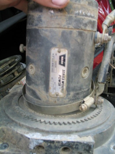
Ok.... tonight's project was to tear into the motor to ensure it was in good shape.... here is what I found.... please note this is the NEW version of the 12K winch. I believe this happened around the break of the century so if you have a 95 / 96 you likely have a different solenoid pack...
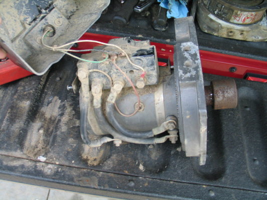
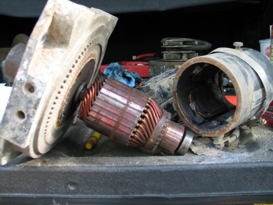
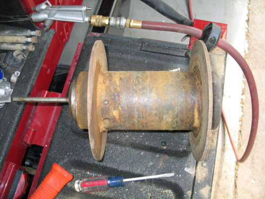
The motor assembly
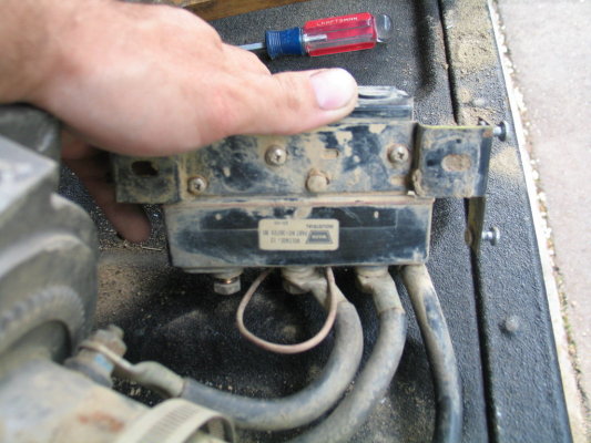
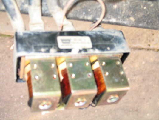
Controller / Solenoid Pack
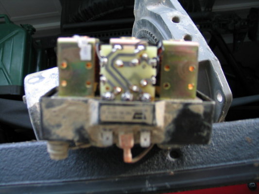
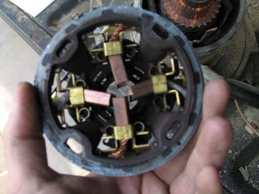
Internals of Controller / Solenod Pack
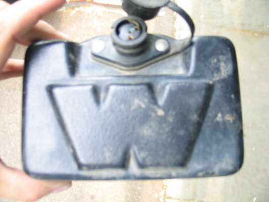
Winch Controller Plug Housing - Top
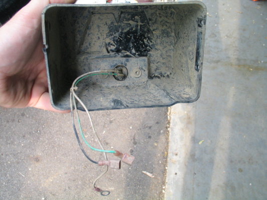
Winch Controller Plug Housing - Bottom
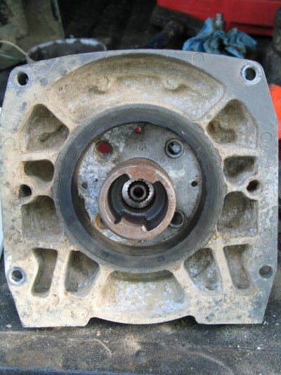
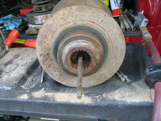
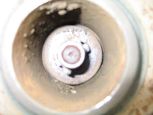
Motor Drive Shaft
Motor Assembly
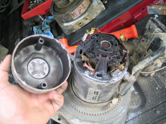
Motor Top Cover Removed
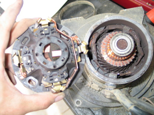
Motor Brush Assembly Removed
Motor Brushes - Bottom Side
Motor - Windings / Shaft
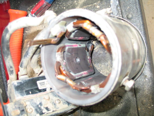
Motor - Magnet Housing
Drum - Gear Housing Side
Drum - Driven / Motor Side
Drum Assembly
I picked up my tub of water proof wheel bearing grease today so likely tomorrow I will start to put it all back together.... that is once I get that damn allen head out....
Here are some of the articles from the Field Fix that Gil puts on... great information. The instructional guide to dissassembling the winch is by Warn.
phazer42
Sensible point on marking any mating surfaces before splitting them. Where possible I also like to replace bolts in the holes they came from. Sounds anal, but if you don't pay attention you can sometimes find that they're different lengths and you didn't note which goes where. Additionally, the threads will mate better with their original partner, which sometimes makes the difference between one of them stripping or not. Gulf1
To allow you to track bolts (and other things that are positionally important yet not visibly different) take a small piece of cardboard, punch a bunch of holes in it matching the item you are disassembling (with a mark to show a starting position such as 'top') and push each bolt into a matching hole in the cardboard. Works for pushrods and other similar things too. When disassembling lay things out on the workbench in the order that they come apart, laying each part down on the bench such that you pick it up and slide it in later facing the same way! (OK, a large, long workbench helps for this, or use a sheet of cardboard on the floor of your garage if you have to, just lay things out in order.) Nehog
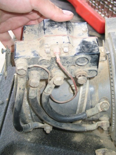
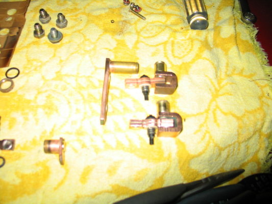
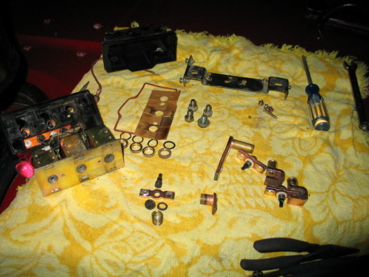
Relative to the orienting of the bolts.... the ones that came out were, for the most part, different sizes / diameters and are easy to differentiate as to which ones go where.... normally I would just take the bolts and put them back in the part they came out of, or use the same idea Nehog states with cardboard.... The long bolts that hold the housing together for the gearset are small and one of them didn't want to come out.... after spraying it with PB blaster it came out.... but it appears there might be some corrosion going on between the aluminum housing and the steel bolt.... but that would be one to watch as you wouldn't want to break the bolt off in the housing.... OK.... now remember this is for the "newer" version winch as this version only has 3 solenoids compared to the 4 in the older versions.... I finshed my overhaul of my winch.... when I hooked it up to reel in the line, I found that it wasn't completely right.... so I started to mess with things again.... I found there was a problem with the solenoid pack control box..... in this version of the Warn M12000 there are 3 solenoids with a few brass bars that are used to pass the current between them..... here are the parts:
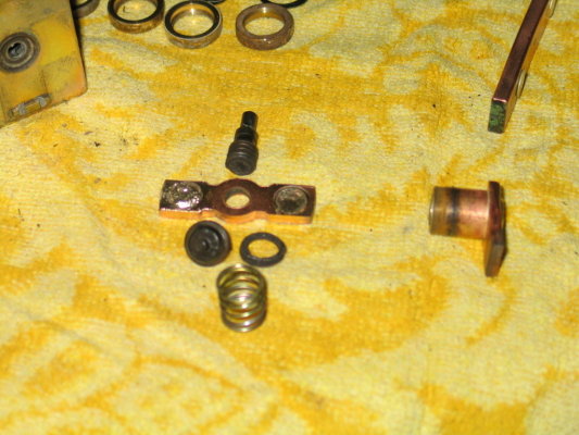
These are the two "bobbers" as I will call them which transfer electrical current to the respective side of the motor for spool in or spool out.... These are activated similar to the CTIS valves, where when the solenoid is energized they raise and lower to transfer energy....
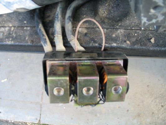
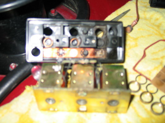
Kinda blurry, but here is the solenoid pack with the simple printed circuit board.....
This is the "bobber" that broke in my control box.... it just happens to be the one that transfers the positive current through the system.... it must have been to hot and melted in half or something..... in any event, I need a new one....
The symptoms of my winch when I got it back together were.... it would spool in then hesitate, then work then hesitate and then completely stop.... phazer42 |