| Forum | Marketplace | Knowledge Base | | H1 site | H2 site | H3 site | |

The Hummer Knowledge Base
|
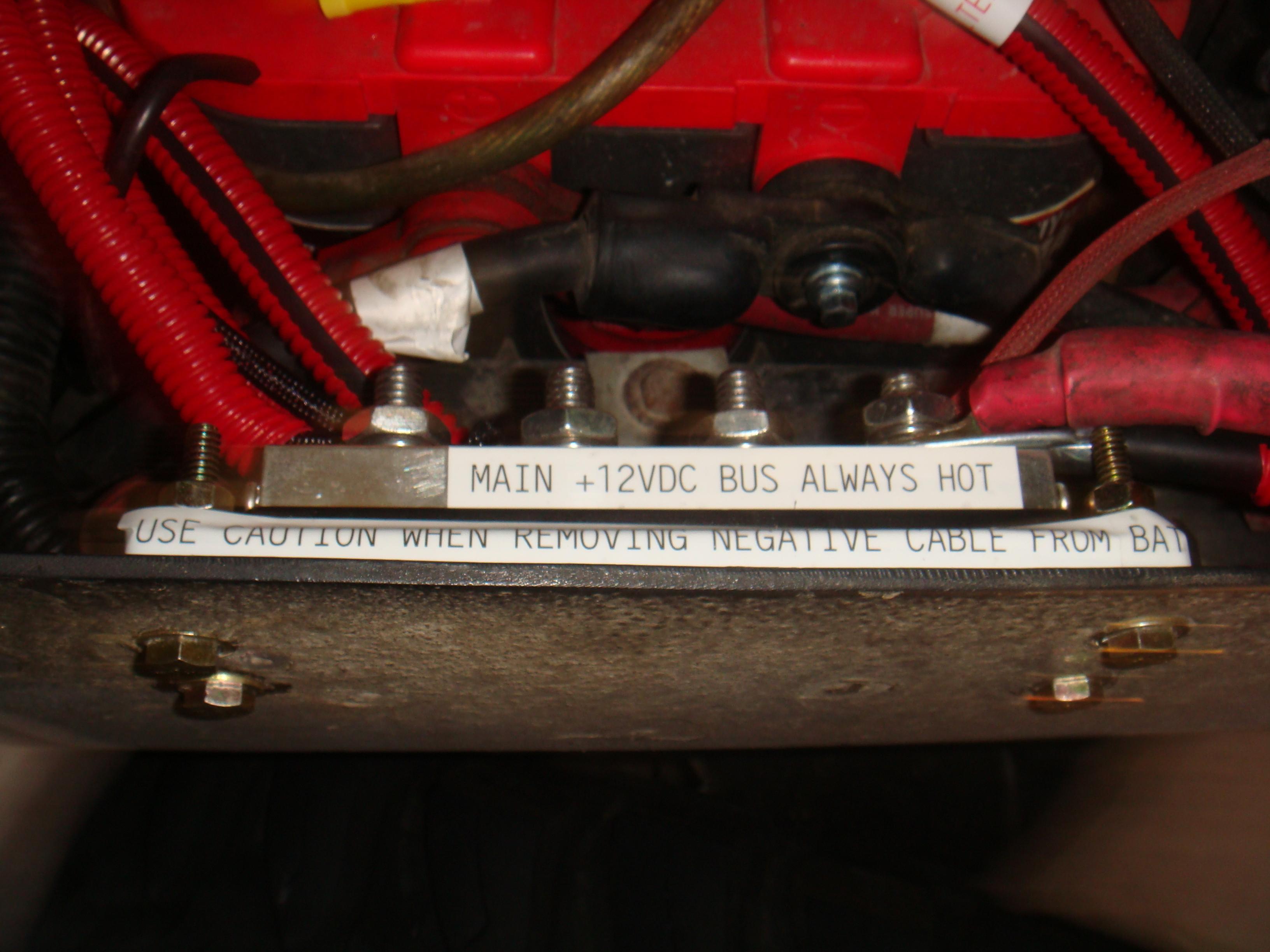
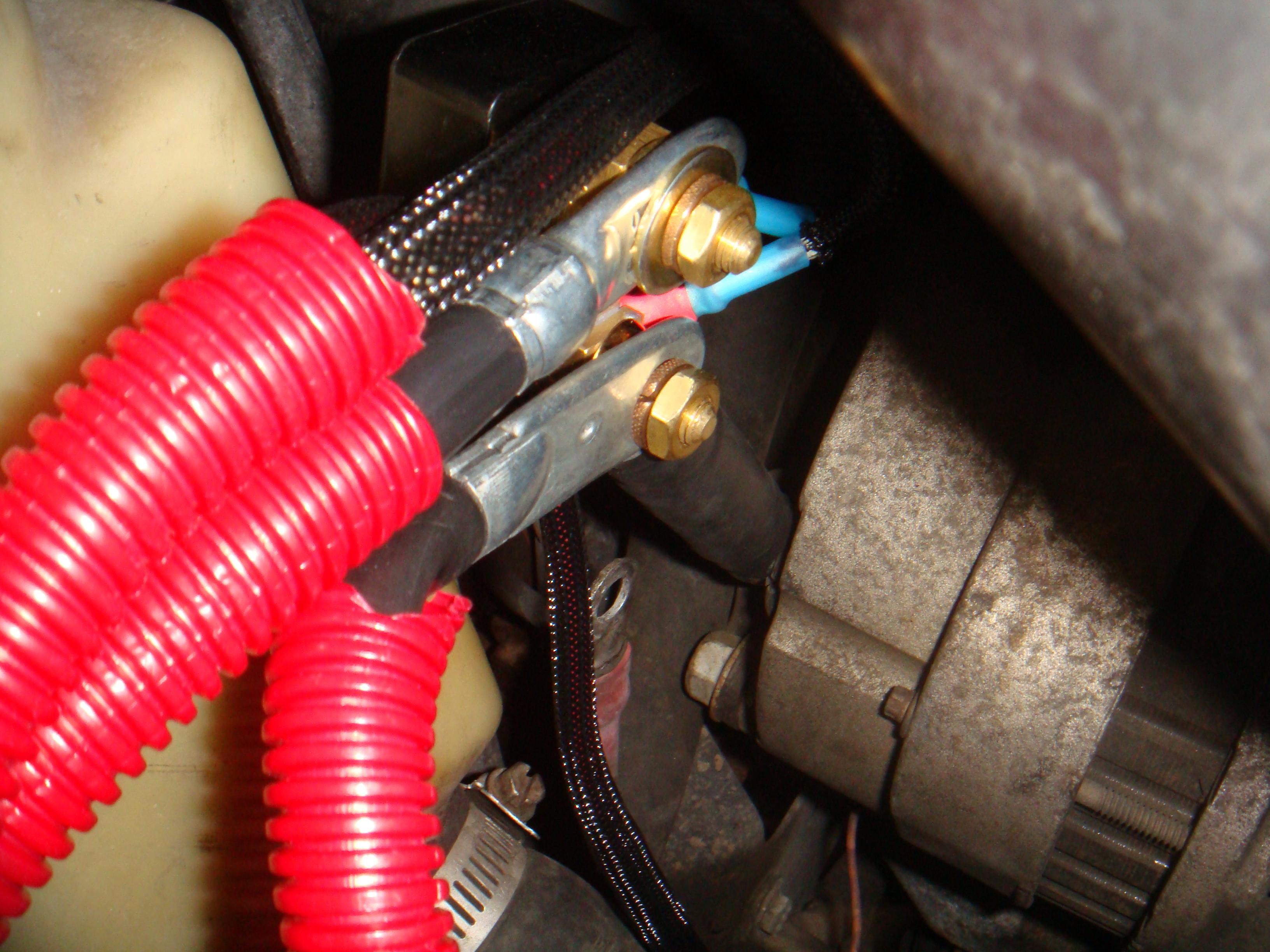
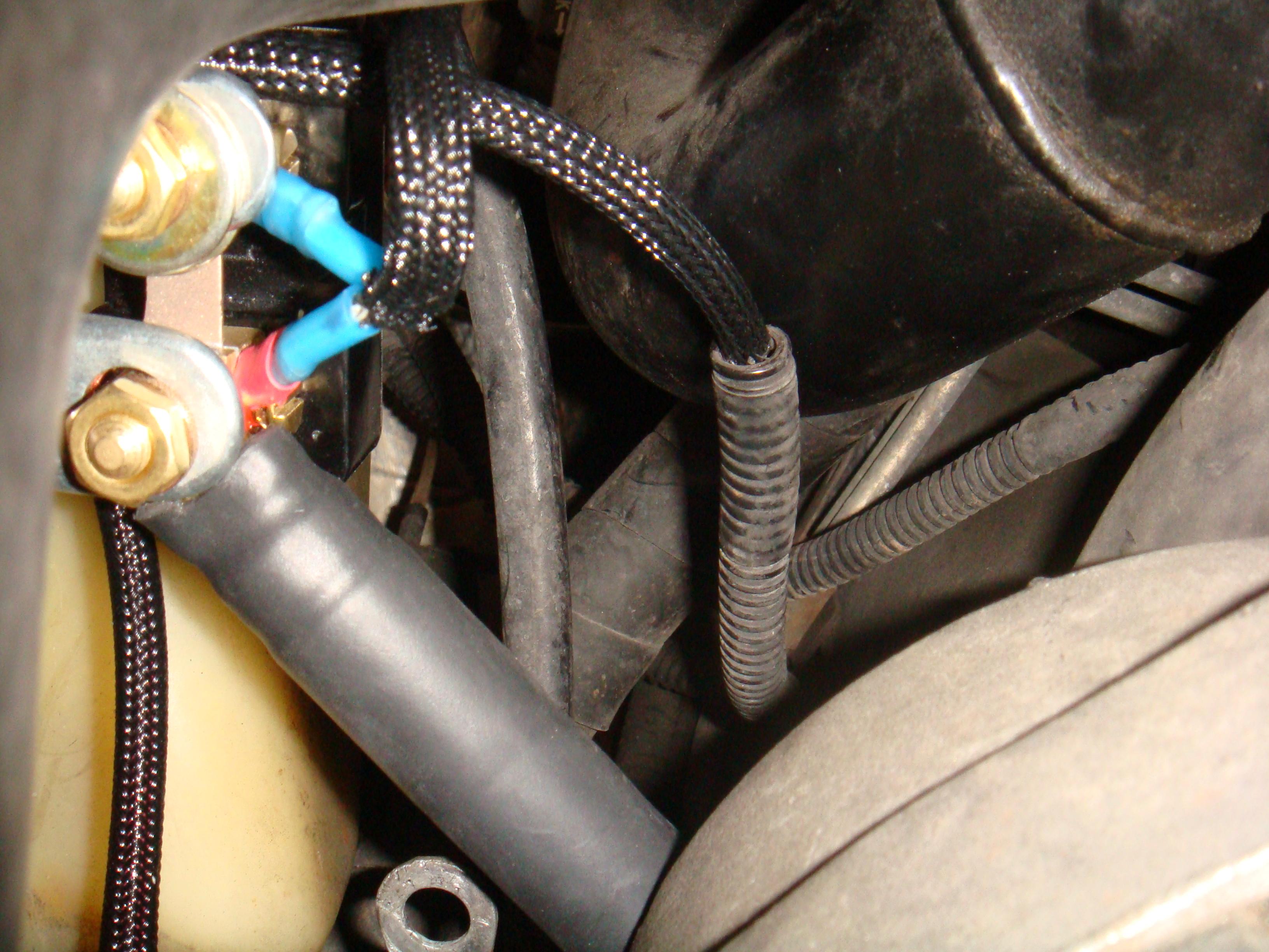
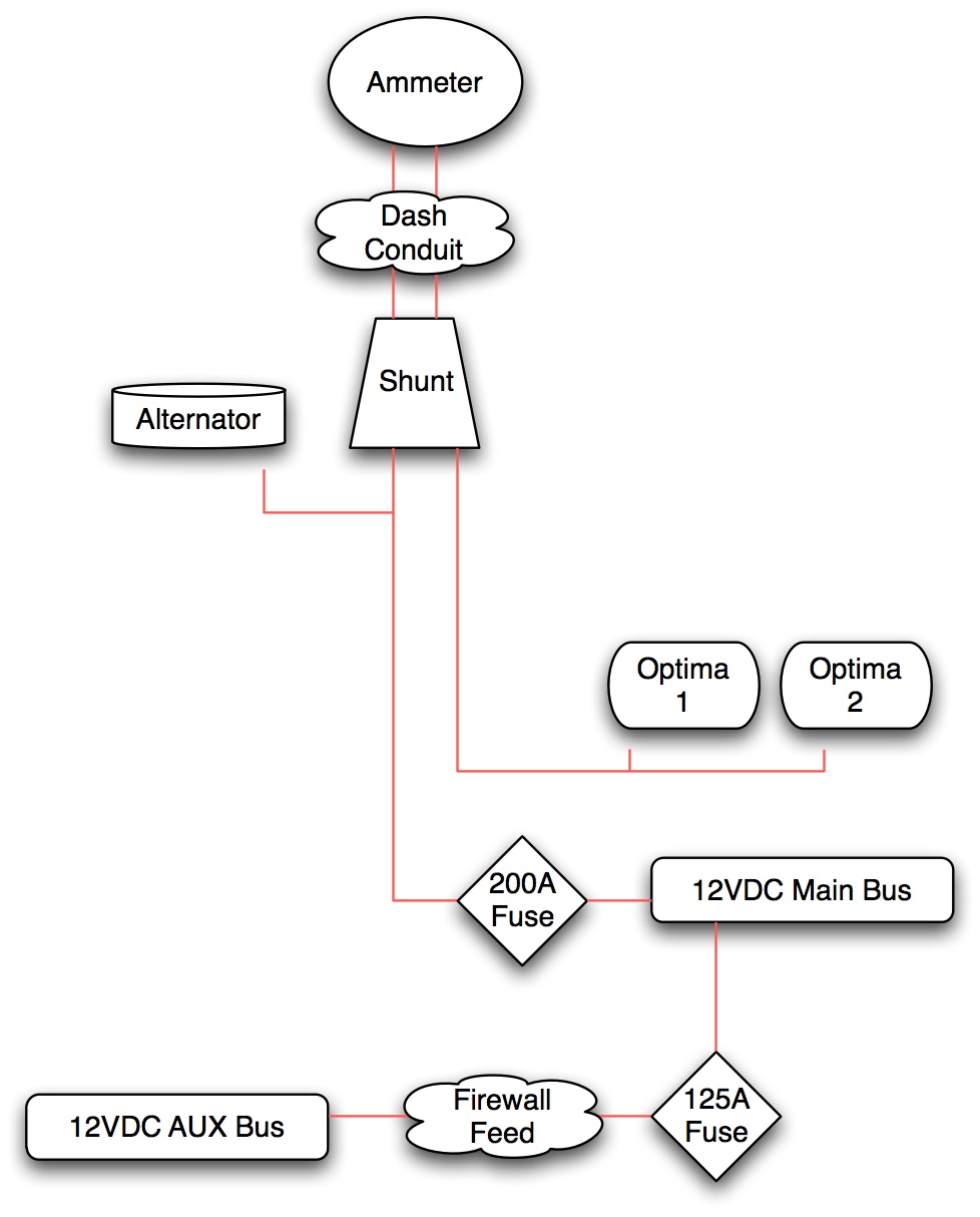
I used a dual ammeter/voltmeter from westach you can get them built for whatever range you want. They also sell the shunts which can measure one current and carry another. For example, the one I am using develops a full 50mv at 100amps, but is rated for 300amps. This allows you to "scale" in a way to see smaller changes in current. First off, This task isn't hard, but you are playing with electricity and can kill yourself and you truck either directly or by letting something get hot and catching it on fire. To do this you are going to have to relocate several feeder wires as AM General decided to use the alternator stud as a buss-bar so there's at least two things attached there, possibly more if someone's been bad. The reason IMO you don't want to do this is that any kind of short in any of those wires transforms your perfectly working alternator into a doorstop. It also makes diagnosing electrical problems (ground loops) a joy as you now have multiple paths for all those electrons to wander around and get lost in as inevitably people hook stuff up to the battery too. Oh wait, someone said "But those feeders have fusible links!!" My personal opinion is that fusible links are a evil spawn of a corporate cost-reduction group. If I have a problem, please .. by all means, protect my precious vehicle, but don't leave me with a conduit full of slag. Just put a big ol' fuse in line and pop that. The trip to walmart to obtain a replacement is punishment enough vs having to rebuild an entire feeder set. (and given the lines on the weekend, about the same amount of time). What I did was to build a bracket off the output stud of the alternator out of a copper bus bar made out of some crappy jumper cables I had busted a while back. The thick piece of copper spent a little time on the bench and in the end I had something that looked like this o--o and given the rating of the jumper cables, it should easily handle many hundreds of amps. This was covered with a nice piece of heat shrink so now it looks like o==o with just the holes uncovered. (sorry no pictures this was built months ago) This bar was mounted to the alternator stud and the positive pole of the shunt was mounted onto the opposite hole. Lock washers on either side were used to hold it in place. It sticks out of the alternator about 2" or so. The shunt mounts there as well as the main feed for the truck (in my case its a link over to the 12vdc main buss I built in the battery well (see pictures below) I figured if you were gonna cut it, cut it out and do it right. You'll be able to see the old eyelet for the original feeder wire still mounted where it goes naturally. I left it there in case the truck developed problems with my changes, but after nearly a year, its going to get pulled out when I have things on that side pulled apart for some reason. The way I have it hooked up is the current "for the truck" is being measured. If its on the + side, the power is coming from the alternator, on the - side power is coming from the battery. Normally it runs about 5amps after the battery is finished charging, turn all the lights on and the AC and it will make it up to 20-something .. Key down on my HF radio and it will swing almost to 40amps.
MrWizard
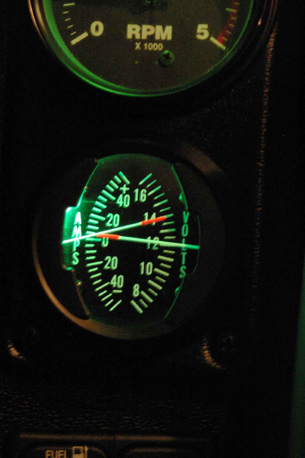
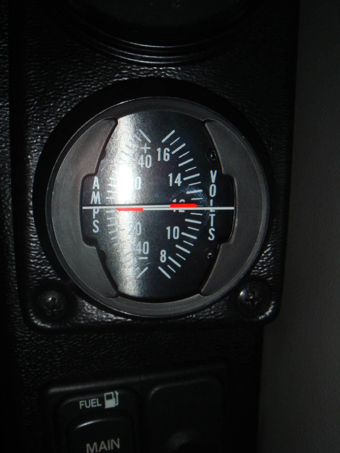
I'd just like to make one correction, the ammeter pic that you have, you have it labeled "Engine running, looks like she pulls about 5amps to keep things going." its positive so it shows your surplus of amps, in normal operations the ammeter should read zero. The ammeter won't show actual amp usage it only shows surpluses (charging the batteries) or deficiencies (draining the batteries) we use them on airplanes all the time and I will be adding one to my truck when its done. True enough, in this configuration, except we've still got a little stuff running out the battery side. That's what's soaking up the amps there. (plus the charging cycle) The alternator doesn't respond quickly, especially at idle. A lot of times there are some good swings from the discharge side as current is pulled from the battery and then a reverse swing as the alternator catches back up and charges the battery.
Just out of curiosity, what does an amp meter tell you when you're driving? I have seen them in various vehicles, even from the factory. Always curious why they have that vs. volt meter. There are a lot of ways to use them, In this example it tells you if your currently "charging" the battery or drawing power from the battery. Its a little more complicated than just "pure load" ( which is another way to set this up ) Right now current flows from the battery through the shunt either forward (discharge) or backward (charge) The amounts are measured on the meter. If the engine is running there should always be a charge. As you load the truck the output will increase from the alternator. If you exceed the output of it (such as a HF amp or heavy use of lights at idle) you'll see it drop below the 0 line and draw surplus power from the batteries. I am not dogging your idea, I currently have a draw that is slowly draining my battery so this setup would allow me to find that draw alot easier! This is probably not the way to do that. Its better to just use a normal DVOM with a decent AMP range and a process of elimination by pulling fuses until you find the suspect circuit, then chase it down from there.
A useful analogy which is helpful, though not perfect, is to think of your battery as a water tank and you draw water (electricity) from a pipe at the bottom. Think of the voltmeter as a level gauge for the water tank, just like a gas gauge. As the tank is filled the pressure at the pipe in the bottom increases. Assuming a light bulb runs on water, when the tank is full it will be nice and bright and as the level drops it will get dimmer, just like a real bulb as the voltage drops in your battery. Think of the ammeter as a flowgauge for the water (electricity) that flows in or out of the tank. It flows out to power any of the electrical items in the vehicle, and it flows back in (to keep the level in the tank nice and high) from the alternator. The ammeter measures both the outflow as a negative figure, and the inflow as positive reading. In theory the alternator will balance the amount used with the amount it generates so the ammeter will read zero. In practice, the alternator often plays catchup, so you will see swings in the reading as electrical useage varies. Not perfect, but it should help to visualize the issue. Oh, and the ammeter vs. voltmeter question? A voltmeter is much cheaper for the manufacturer to install. Gulf1 |